Advanced extensible Interface(AXI) is an on chip bus communication protocol developed by ARM.
This blog post is about creating a custom IP with one MAXI (Master-AXI) port. One MAXI port can communicate with one or multiple Slave-AXI ports of other IPs. Generally on FPGAs, it is used to connect to memory such as DDR3/DDR4 or HBM memory supported by Xilinx Ultrascale + families.
Here, I will create an IP in c++ language by using Xilinx Vitis HLS 2022.1 version.
I will then export the IP and make a project in Vivado 2022.1 for Zybo z720 FPGA development board from Digilent, then write the SDK code, then load Bitstream on hardware and see the results on ILA.
ILA is used to analyse signals of RTL, you can find out more about it here
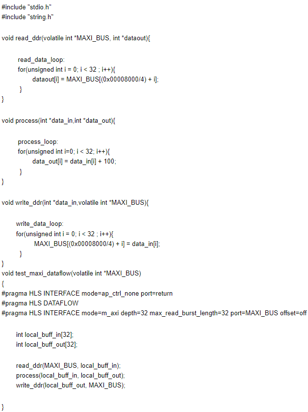
The code below does the following steps:
- Reads 32 packets of data from memory, where each packet is 32- bit using the read_ddr function and then store it in a local_buff_in array.
- Update the contents of local_buff_in by adding +100 and storing to local_buff_out array
- Write 32 packets of local_buff_out to memory, where each packet is 32-bit using write_ddr function

Pragmas
Pragmas in general are pre-processor definitions which are evaluated before the code starts to compile. You can learn more about interface here.
#pragma HLS INTERFACE mode=m_axi depth=32 port=MAXI_BUS offset=off
The first pragma (i.e #pragma HLS INTERFACE mode=ap_ctrl_none port=return) will not create a axilite interface which is used to control and monitor the functionality of IP.
The second pragma (i.e #pragma HLS INTERFACE mode=m_axi depth=32 port=MAXI_BUS offset=off) is important to create MAXI port on this IP. Not using this pragma will not create a proper functional MAXI port.
Using the offset = slave parameter of this pragma, sets the address to read/write on axilite port.
It supports three options:
- Offset = slave
Creates axilite ports of address read/write - Offset = direct
Creates 32-bit input port on IP - Offset = off
Uses internal address, by default starts on zero
The parameter depth = 32 is optional, however it is better to have this parameter change if you know how much data you want to read.
The function read_ddr(MAXI_BUS, local_buff_in); will create MAXI read transaction. It will read data from memory and store it into local_buff_in variable
The function process(local_buff_in, local_buff_out); will update the contents of local_buff_out variable.
The function write_ddr(local_buff_out, MAXI_BUS); will create MAXI write transaction, it will write data to memory.
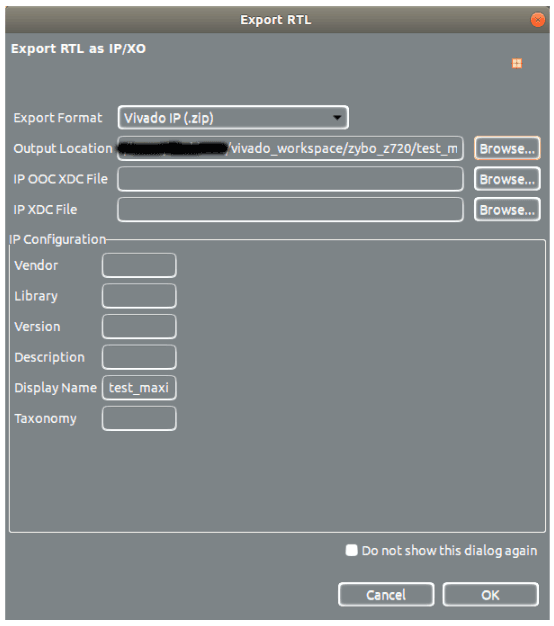
Next, I will export the IP:

Once this dialogue box appears:
- Choose Export Format as Vivado IP
- In Output Location choose your preferred location on your drive
- In Display Name type in your preferred name
Next:
- Launch vivado
- Create a new project with Zybo z720 as target FPGA
- Add the IP in IP catalogue
I have provided the TCL script to create a project from scratch. Below is the block design for reference:

Once the block design is made, then make an HDL wrapper and generate bitstream.
After generating bitstream, export design1_wrapper.xsa file to your preferred location, which is used to create the Vitis SDK code.
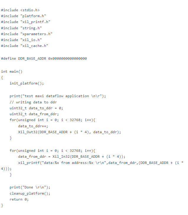
Below is the SDK code:

Some notes about this SDK code:
- #include "xparameters.h": this header file contains address map of your block design
- #include "xtest_maxi.h": this header file is generated by Vitis_HLS tool which contains all the API function call related to IP.
The SDK code does the following steps:
- Write some data to DDR memory using Xil_Out32 function
- Read some data to DDR memory using Xil_in32 function
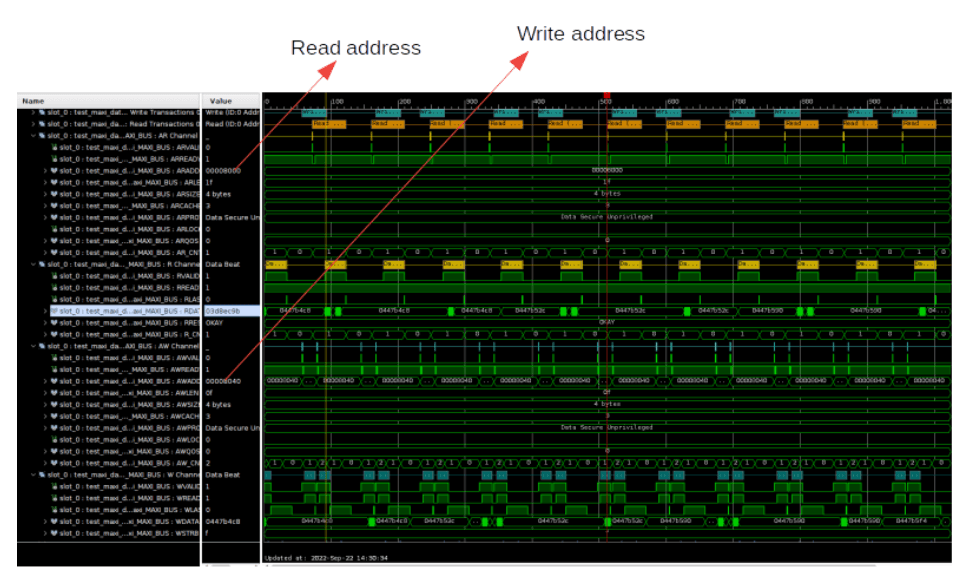
Below is the ILA screenshot of data read:

